1.1 Motivation
The US Department of Labor (2007) demonstrated that crane power line contact has been the primary killer on construction sites in the USA for the last 20 years. Crane power line contact occurs when a crane comes into contact with an energised power line. Suruda et al (1997) state that electrocutions amount to approximately 44% of total construction fatalities when a crane was involved and Morgan (1992) estimates 100 power line incidents occur each year.
1.2 The Problem
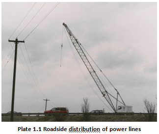
The Code of Federal Regulations (2002) stipulates that no part of a crane, or its suspended load, is allowed to work within 3.05 metres (10 feet) of a 50 kilovolt (kV) line and to effect this a dedicated spotter is used to warn the crane operator when any part of the crane breaches the 10 ft distance. Cunitz and Middendorf (1985) put forward several explanations for why a crane could hit an apparently harmless power line; these include poor lighting conditions, over familiarity on the part of the operator, poor training and bad judgement, but that the primary cause was that human eyes are unable to gauge the distance between the crane and power line against an undistinguished sky, plate 1.1. Cunitz and Middendorf observe that the lack of either shadow or other objects against which to make a visual comparison is significant in creating this effect.
Turner (2004) expresses 20/XX as a measure of visual ability, and can be expressed with 20 ft (6.09 m) as the numerator and the denominator XX being the ability to recognise characters measured in minutes of an arc. On this scale of measurement 20/20 is considered normal, 20/40 is half normal and 20/10 twice normal. Turner suggests a dedicated spotter, with uncorrected vision, should have eyesight of at least 20/13, which is 30% better than normal.
BC Hydro (2003) suggest that when a crane contacts a power line the ground underneath the crane will become energised as the power flows from the power line down the crane, through its out-riggers and tyres, to the ground. At some distance from the crane, which is a function of soil type and moisture, the ground will be at zero volts, figure 1.1.
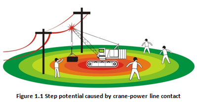
BC Hydro (2003) suggest that a person within this area is in direct danger either by touching any conductive part of the crane or even walking across the potential gradient. This situation can result in fatalities due to the ‘step potential’, which is the voltage difference between the two feet, being sufficient to pass a current through the heart causing fibrillation. Their approved and safe manner to exit this danger area is to shuffle or hop. In this way no potential gradient or difference will exist between the two feet, as they will be at the same physical point hence the same voltage. Mousa (1990) suggests this area of danger extends to a distance of 1.2 m from any conductive part of the crane touching the ground when energised with 25 kV.
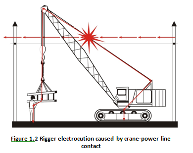
MacCollum (1993) identifies three types of personnel in contact with a crane: the driver, the bystander and the rigger. “Oiler” is a generic name for any bystander in contact with the crane and ground. The rigger attaches the load to the hook of the crane and often guides the load being lifted by means of a line called a tag line. MacCollum quotes that in 70% of crane-power line contacts the rigger was electrocuted as current passes from the crane-power line contact through the crane and rigger to earth, figure 1.2.
The crane operator sits in a metal cab, effectively a Faraday cage, and the power flows around the cab and thus the crane operator was safe. Hitting the power line often disables the controls of the crane and so the crane operator was unable to swing the crane away from the powerline. The crane operator must have the self-discipline not to leave the cab until the power was turned off by the electric utility whilst watching, yet unable to help, co-workers being killed. The crane operator’s situation becomes more dangerous if the crane catches fire, forcing the operator to jump without touching the crane and ground simultaneously. The crane operator subsequently has to leave the area in the safe manner described above to avoid ‘step potential’. The oilers are almost always killed, or badly injured, unless the power line contacted the lifted load below an insulating link.
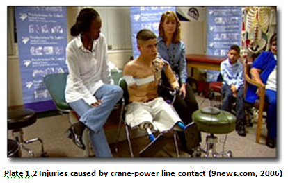
Accidents of this nature also give rise to many serious injuries each year including burning off all limbs, plate 1.2. This type of crane accident occurs in a range of countries, including the USA, where distribution power lines are carried on roadside poles often using unsheathed wires, plate 1.1. In the UK these same distribution power lines are usually buried in the road with the exception of rural situations.
1.3 The possible solutions
When a crane hits a power line it is already too late to consider precautions such as barricades, spotters, flags, limit stops and other procedures. One solution is to interrupt the power supply at the power station, by a circuit protection device, when it senses a dramatic surge in current as the power flows from the power line through the crane to earth. Goff (nd) explains that these circuit protection devices are fitted with an automatic re-closing feature that will re-energise the power line within a few seconds to maintain the supply of electricity. Richmond Power and Light (2010) suggest that electric utilities are reluctant to de-energise power lines as this may interrupt power supplies to hospitals and other key establishments. The only alternative to de-energising power lines incurs substantial rerouting costs and dislocation to allow a one-hour crane operation to occur.
Another solution was to protect workers by insulating them with high-voltage protective clothing. This clothing was usually made from some form of rubber which was able to mould to the shape of the body and provide a continuous unbroken surface to stop the flow of electricity. ASTM (2002) requires that the rubber should be in the order of 12 millimetres (mm) in order to be able to resist 25 kV. A second pair of leather over gloves is required on top of the rubber gloves in order to protect them from abrasion or puncture, which could prove fatal as a high-voltage will flow through a tiny hole or tear. The author suggests that these double glove solutions are both cumbersome and impractical for continuous work in the construction crane environment.
Another solution is to use a nonconductive lifting rope instead of a wire rope on a crane in order to insulate the crane from the load that is being lifted and in contact with the crane worker. North (2010) reports that there has been little change in wire rope lifting in approximately one hundred years, rather it was the demand for passenger elevators in mining that have brought dramatic changes to the design of lifting ropes. The lifting rope on a crane experiences abrasion as it passes over the many pulleys and on and off the rotating drum on which the rope was stored. This is the historic reason why a wire lifting rope has been used. North explains that developments in polymer ropes have brought the benefit of low weight but still have serious issues to overcome; ultraviolet radiation degradation, low notch toughness, swelling water, creep under load, inability to dissipate heat generated during lifting and inadequate load resistance to compression during storage. Even if these mechanical problems can be overcome a polymer lifting rope you will conduct electricity when it was wet or contaminated.
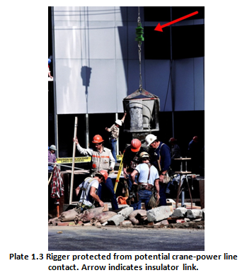
Another solution to protect workers in the vicinity of the crane was to insulate them from the energised crane by the use of an insulating link, see plate 1.3; this will be discussed in the next section.
1.4 A proposed solution
A proposed solution to the problem of electrocution from crane power line contact is to fit an insulating link between the lifted load and the crane hook, plate 1.3. The insulating link’s performance must take into account the expected operating mechanical loading and high voltage conditions and should never pass an ‘unsafe’ current.
Ingram et al (1959) patented an insulating link in the USA thus allowing Mississippi and Arkansas and, in 1965, Federal law 8C-29 to mandate the use of insulating links. On behalf of the crane companies Morgan (1982) examined the available insulating links and decided that they were unsafe as they passed lethal currents when wet or contaminated. Subsequently the Federal law was repealed and the use of insulating links was discouraged.
The novel insulating link, designed, developed and tested in this research, provides a breakthrough in performance, being safe to use when wet or contaminated. Pittman (2003) and Redeker (1999), appendix 1, suggest this breakthrough left the crane industry with a dilemma for if they openly acknowledged the insulating link’s safe performance they would be sued if they did not fit them. After several years of the crane industry not fitting insulating links, the Department of Labor (2008) decided that the continued unnecessary death of crane workers should stop. In 2004 OSHA charged CDAC with rewriting the 30-year-old Construction Crane Safety Standard 29 CFR 1226.550 relating to cranes and derricks safety, which was aided by Pratt. The rule was published 8th August 2010 with an implementation date of 8th November 2010.
1.5 A proposed standard
The Department of Labor [2008] stipulates that the ‘insulating link’ should be tested and approved by an NRTL to protect US citizens from unsafe products describing themselves as insulating links but ineffective as protective devices. The NRTL cannot test an item unless it is tested to a recognised standard and the NRTL has been authorised to have such products included in its scope of work.
As no recognised standards existed for insulating links it was necessary to create one from the Pratt’s Standard Insulating Link Tests (SILT) (2000), which was reformatted and improved to make it compatible with IEC or International Standards. A standard needs a home, which could be a National or International Standard body. The UK Minister of Trade would not support a BSI Standard for a UK design as the principal beneficiaries, the crane riggers, were in the US.
The draft Standard was offered between 2004 and 2008 to various ISO committees including ISO TC 96, (cranes), ISO TC 111, (chains) and IEC committees including IEC TC 78, (live line working) and IEC TC 36, (insulators). All committees recognized the problem was serious and needed addressing but was either ‘outside their scope’ or politically unacceptable.
IEC (2008) stated that the SMB of the IEC should liaise with the TMB of the ISO to propose a joint working program using the Mode 5 cooperation agreement to publish a double logo IEC/ISO publication. TC 36, the insulator committee, set up an ad-hoc group to establish whether standardization was currently required for crane insulating links. Pratt, as Rapporteur for the ad-hoc working committee for TC 36, recommended approval. The French and Germans voted against producing a standard, and were supported by the US members of ISO TC 96, who voted against their US National policy. As a result, this proposed IEC/ISO Standard failed to be supported on the IEC/ISO route.
Undeterred, work continued to refine and test the novel insulating link to see if it met the rigours of the draft standard. In the draft standard there are many insulator tests, which are very well known and understood forming the basis of key IEC insulator standards. One of the key elements was to understand what happens when an insulating link was contaminated with a material that could increase the passage of current. In 2000, contaminated testing of insulators was in its early stages and had not matured into full standards. Pratt was a member of an international technical working group for insulators CIGRE WG C4.3.03 that provided the material for the subsequent IEC60815 contaminated insulator Standards completed in 2008. There are two distinct phases of performance, the first initial transient and subsequent steady-state currents. The real focus of attention was to quantify this transient current and to compare it with allowable currents that have been accepted in the industry for humans in contact with a source of electrical energy. It was not known whether these transient currents would harm or kill. It was the purpose of this standard to construct a test so that these currents could be reliably measured, analysed and compared so that an insulating link could be deemed safe or not.
References:
- BC Hydro 2004 Workspace Safety On line available at:
http://www.bchydro.com/safety/workplace_safety/7_steps_to_electrical_safety.html - Code of Federal Regulations, 2002. 29 CFR 1926 – Labor. Washington, D.C.: U.S. Government Printing Office
- Cunitz R.J. and Middendorf L. 1985. Problems in the perception of overhead power lines. Hazard Prevention, 21(2), 19-23
- Goff L.E. Automatic reclosing of distribution and transmission line circuit breakers. General Electric Company GER – 2540 A [online] Available at:
- Hipp, J.E., et al 1982. Evaluation of Proximity Warning Devices. Bureau of Mines Final Report, Contract JO188082. Washington, DC: Superintendent of Documents.
- MacCollum D. V. 1993. Crane hazards and their prevention. Des Plaines, IL: American Society of Safety Engineers
- Morgan D. 1992. Deposition Muszynski v. Union Oil Company et al. s.l.: s.n.
- Mousa A.M. 1990. Protecting firemen against fire-induced flashovers. IEEE Transactions on Power Delivery, 5(1): 297-302
- The National Institute for Occupational Safety and Health. 2008. A Performance Evaluation of Two Overhead Power Line Proximity Warning Devices. NIOSH Information Circular 9510: US Dept. of Health and Human Services
- Suruda A. et al. 1997. Crane related deaths in the US construction industry 1984-94. Center to Protect Workers’ Rights, Report D2-97. Washington D.C.:CPWR